Gujarat Board GSEB Textbook Solutions Class 12 Physics Chapter 7 Alternating Current Textbook Questions and Answers, Additional Important Questions, Notes Pdf.
Gujarat Board Textbook Solutions Class 12 Physics Chapter 7 Alternating Current
GSEB Class 12 Physics Alternating Current Text Book Questions and Answers
![]()
Question 1.
A 100 Ω resistor is connected to a 220 V, 50 Hz ac supply.
(a) What is the rms value of current in the circuit?
(b) What is the net power consumed over a full cycle?
Solution:
(a) Irms = \(\frac{\mathrm{V}_{\mathrm{rms}}}{\mathrm{R}}\)
= \(\frac { 220 }{ 100 }\)
(b) Power = Vrms.Irms
= 220 x 2.2 = 484 W
Question 2.
The peak voltage of an ac supply is 300 V. What is the rms voltage?
The rms value of current in an ac circuit is 10 A. What is the peak current?
Solution:
(a) Vrms = \(\frac{V_{\max }}{\sqrt{2}}\)
= \(\frac{300}{\sqrt{2}}\)
= 212.1 V
(b) Irms = \(\frac{I_{\max }}{\sqrt{2}}\)
∴ Irms = \({\sqrt{2}}\).Irms = \({\sqrt{2}}\) x 10 = 14.14 A
Question 3.
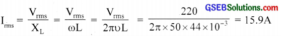
A 44 mH inductor is connected to 220 V, 50 Hz ac supply. Determine the RMS value of the current in the circuit.
Solution:
Question 4.
A 60 µF capacitor is connected to a 110 V, 60 Hz ac supply. Determine the rms value of the current in the circuit.
Solution:
= 2πυC x Vrms = 2p x 60 x 60 x 106 x 110 = 2.5A
Question 5.
In Exercises 3 and 4, what is the net power absorbed by each circuit over a complete cycle? Explain your answer.
Solution:
No power loss in the case of an ideal inductor or ideal capacitor.
![]()
Question 6.
Obtain the resonant frequency ωr of a series LCR circuit with L = 2.0 H, C = 32 µF and R = 10Ω. What is the Q-value of this circuit?
Solution:
ωr = \(\frac{1}{\sqrt{\mathrm{LC}}}\)
= \(\frac{1}{\sqrt{2 \times 32 \times 10^{-6}}}\)
= 125 sec-1
Q = \(\frac{\omega_{\mathrm{r}} \mathrm{L}}{\mathrm{R}}\)
= \(\frac { 125×2 }{ 10 }\) = 25
Question 7.
A charged 30pF capacitor is connected to a 27 mH inductor. What is the angular frequency of free oscillations of the circuit?
Solution:
ωr = \(\frac{1}{\sqrt{\mathrm{LC}}}\)
= \(\frac{1}{\sqrt{27 \times 10^{-3} \times 30 \times 10^{-6}}}\)
= 1.11 x 10³ Sec-1
Question 8.
Suppose the initial charge on the capacitor in Exercise 7 is 6 mC. What is the total energy stored in the circuit initially? What is the total energy at later time?
Solution:
E = \(\frac{\mathrm{Q}^{2}}{2 \mathrm{C}}\)
= \(\frac{\left(6 \times 10^{-3}\right)^{2}}{2 \times 30 \times 10^{-6}}\)
= 0.6 J
Total energy is same for the later time.
![]()
Question 9.
A series LCR circuit with R =20 Ω, L = 1.5 H and C = 35µF is connected to a variable frequency 200 V ac supply. When the frequency of the supply equals the natural frequency of the circuit, what is the average power transferred to the circuit in one complete cycle?
Solution:
L= 1.5 H
C = 35 µF = 35x 10-6 F
R = 20q
Ev = 200V
When the frequency of the supply equals the natural frequency of the circuit, the impedance of the circuit is equal to the resistance of the circuit. Therefore, rms value of the current in the circuit
\({ I }_{ V }=\frac { { E }_{ v } }{ R } =\frac { 200 }{ 20 } =10A\)
Therefore, average power transferred to the circuit in one complete cycle,
P =E I =200×10 = 2000 W.
Question 10.
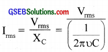
A radio can tune over the frequency range of a portion of the MW broadcast band: (800 kHz to 1200 kHz). If its LC circuit has an effective inductance of 200 µH, what must be the range of its variable capacitor?
[Hint: For tuning, the natural frequency i.e., the frequency of free oscillations of the LC circuit should be equal to the frequency of the radio wave.]
Solution:
Hence range of the capacitor is from 88 pF to 198 pF.
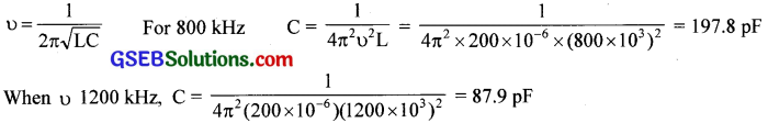
Question 11.
Figure shows a series LCR circuit connected to a variable frequency 230 V source. L = 5.0 H, C = 80 µF, R = 40 Ω.
(a) Determine the source frequency which drives the circuit in resonance.
(b) Obtain the impedance of the circuit and the amplitude of current at the resonating frequency.
(c) Determine the rms potential drops across the three elements of the circuit. Show that the potential drop across the LC combination is zero at the resonating frequency.
Solution:
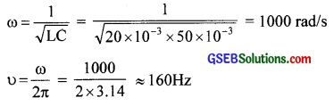
(a) ω = \(\frac{1}{\sqrt{\mathrm{LC}}}\)
= \(\frac{1}{\sqrt{5 \times 80 \times 10^{-6}}}\) = 50 rad/sec.
(b) At resonance
Z = R = 40 Ω
Irms = \(\frac{\mathrm{V}_{\max }}{\mathrm{R}}\)
= \(\frac{230 \sqrt{2}}{40}\) = 8A
(c) VL = IXL = IωL = 8 x 50 x 5 = 2000 V
VC = IXC = \(\frac { I }{ ωC }\)
= \(\frac{8}{50 \times 80 \times 10^{-6}}\)
= 200 V
VR = 230 V
VL – VC = 0
i.e., Potential drop across LC combination is zero.
![]()
Question 12.
An LC circuit contains a 20 mH inductor and a 50µF capacitor with an initial charge of 10 mC. The resistance of the circuit is negligible. Let the instant the circuit is closed be t = 0.
(a) What is the total energy stored initially? Is it conserved during LC oscillations?
(b) What is the natural frequency of the circuit?
(c) At what time is the energy stored
i. completely electrical (i.e., stored in the capacitor)
ii. completely magnetic (i.e., stored in the inductor)
(d) At what times is the total energy shared equally between the inductor and the capacitor?
(e) If a resistor is inserted in the circuit, how much energy is eventually dissipated as heat?
Solution:
(a) Total initial energy = \(\frac{Q^{2}}{2 C}\)
= \(\frac{\left(10 \times 10^{-3}\right)^{2}}{2 \times 50 \times 10^{-6}}\)
= 1J
Yes. If R = 0, then sum of energies for L and C is conserved.
(b)
(c) q = q0 cos ωt and u = \(\frac{q^{2}}{2 C}\). Then
i. Energy stored is completely electrical at t = 0, \(\frac { T }{ 2 }\), T, \(\frac { 3T }{ 2 }\), …..
ii. Electrical energy is zero and energy stored is purely magnetic energy at t = \(\frac { T }{ 4 }\), \(\frac { 3T }{ 4 }\), \(\frac { 5T }{ 4 }\)
T = \(\frac { 1 }{ f }\)
= \(\frac { 1 }{ 160 }\) ≈ 6.2 ms
(d) Energy is shared equally between L and C at \(\frac { T }{ 8 }\), \(\frac { 3T }{ 8 }\), \(\frac { 5T }{ 8 }\) since E = \(\frac{\mathrm{q}_{0}^{2} \cos ^{2} \omega \mathrm{t}}{2 \mathrm{C}}\)
If cot = 45°, cos ωt = \(\frac{1}{\sqrt{2}}\)
∴E = \(\frac { 1 }{ 2 }\).\(\frac{\mathrm{q}_{0}^{2}}{2 \mathrm{C}}\) = \(\frac { 1 }{ 2 }\) of total energy
(e) Total initial energy 1J will be lost as heat due to the joule heating effect in the resistor.
![]()
Question 13.
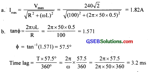
A coil of inductance 0.50 H and resistance 100Ω is connected to a 240 V, 50 Hz ac supply.
(a) What is the maximum current in the coil?
(b) What is the time lag between the voltage maximum and the current maximum?
Solution:
Question 14.
Obtain the answers (a) to (b) in Exercise 13 if the circuit is connected to a high-frequency supply (240 V, 10 kHz). Hence, explain the statement that at very high frequency, an inductor in a circuit nearly amounts to an Open circuit. How does an inductor behave in a dc circuit after the steady-state?
Solution:
ω = 2πυ = 2p x 104 rad/s
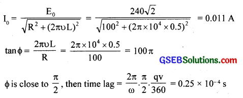
I0 being very small we can conclude that at high frequencies, an inductor behaves as an open circuit.
In Φ circuit, υ = 0. So inductor acts as a conductor.
Question 15.
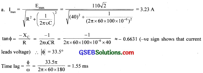
A 100pF capacitor in series with a 40Ω resistance is connected to a 110 V, 60 Hz supply.
(a) What is the maximum current in the circuit?
(b) What is the time lag between the current maximum and the voltage maximum?
Solution:
Question 16.
Obtain the answers to (a) and (b) in Exercise 15 if the circuit is connected to a 110 V, 12 kHz supply? Hence, explain the statement that a capacitor is a conductor at very high frequencies. Compare this behaviour with that of a capacitor in a dc circuit after the steady-state.
Solution:
(a)
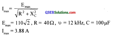
(b) tan F = \(\frac { – 1 }{ ωCR }\) = – 0.2 or F is nearly zero at high frequency. ‘C’ term being negligible at high frequency, it acts like a resistor.
For steady dc, υ = 0 and Xc = ∞. So it acts like an open circuit for dc.
Question 17.
A circuit containing an 80 mH inductor and a 60 µF capacitor in series is connected to a 230 V, 50 Hz supply. The resistance of the circuit is negligible.
(a) Obtain the current amplitude and rms values.
(b) Obtain the rms values of potential drops across each element.
(c) What is the average power transferred to the inductor?
(d) What is the average power transferred to the capacitor?
(e) What is the total average power absorbed by the circuit?
[‘Average’ implies ‘averaged over one cycle’.]
Answer:
(a)
(b) VL = Irms x ωL = 207 V
VC = Irms x \(\frac { 1 }{ ωC }\) = 437 V
(c) Φ = \(\frac { π }{ 2 }\).
So current lags voltage by \(\frac { π }{ 2 }\).
PL = 0
(d) Φ = \(\frac { π }{ 2 }\).
So current leads voltage by \(\frac { π }{ 2 }\)
Pc = 0
(e) Total average power absorbed = 0
![]()
Question 18.
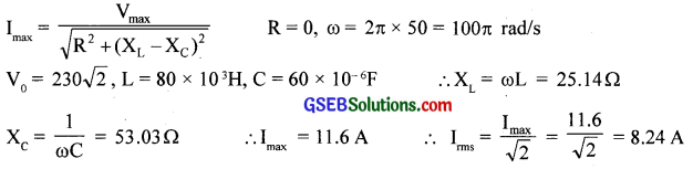
Suppose the circuit in Exercise 17 has a resistance of 15 Ω. Obtain the average power transferred to each element of the circuit, and the total power absorbed.
Solution:
If R = 15 Ω, then Irms = \(\frac{\mathrm{V}_{\mathrm{rms}}}{\sqrt{\mathrm{R}^{2}+\left(\mathrm{X}_{\mathrm{L}}-\mathrm{X}_{\mathrm{C}}\right)^{2}}}\)
= \(\frac{230}{\sqrt{(15)^{2}+(53.03-25.14)^{2}}}\)
= 7.26 A
Average power
PL = PC = 0
PR = Irms2R
= (7.26)2 x 15
= (791) W
Total power consumed = 791 W
Question 19.
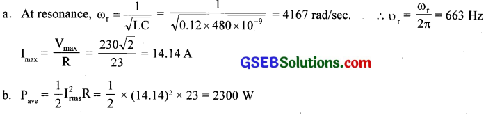
A series LCR circuit with L = 0.12 H, C = 480 nF, R = 23 Ω is connected to a 230 V variable frequency supply.
(a) What is the source frequency for which current amplitude is maximum? Obtain this maximum value.
(b) What is the source frequency for which the average power absorbed by the circuit is maximum? Obtain the value of this maximum power.
(c) For which frequencies of the source are the power transferred to the circuit half the power at resonant frequency? What is the current amplitude at these frequencies?
(d) What is the Q-factor of the given circuit?
Solution:
(c) ∆ω = \(\frac { R }{ 2L }\) = \(\frac { 23 }{ 2 × 0.24}\) = 95.8 rad/sec
∆υ = \(\frac { ∆ω }{ 2p }\) = 15.2 Hz
Power absorbed = Half of υ = 663 ± 15 Hz
Current amplitude = \(\frac{\mathrm{I}_{0}}{\sqrt{2}}\)
= \(\frac{14.14}{\sqrt{2}}\)
= 10 A
(d) Q = \(\frac{X_{L}}{R}\) = \(\frac { ωL }{ R }\)
= \(\frac{4.67 \times 0.12}{23}\)
= 21.7
Question 20.
Obtain the resonant frequency and Q-factor of a series LCR circuit with L = 3.0 H, C = 27 µF, and R = 7.4Ω. It is desired to improve the sharpness of the resonance of the circuit by reducing its ‘full width at half maximum’ by a factor of 2. Suggest a suitable way.
Solution:
ωr = \(\frac{1}{\sqrt{\mathrm{LC}}}\)
= \(\frac{1}{\sqrt{3 \times 27 \times 10^{-6}}}\)
= 111 rad/s
Q = \(\frac{X_{\mathrm{L}}}{\mathrm{R}}\) = \(\frac{\omega_{\mathrm{r}} \mathrm{L}}{\mathrm{R}}\)
= \(\frac { 111×3 }{ 7.4 }\)
For doubling Q for the same ωr, R should be reduced to half and is equal to 3.7 Ω.
![]()
Question 21.
A power transmission line feeds input power at 2300 V to a stepdown transformer with its primary windings having 4000 turns. What should be the number of turns in the secondary in order to get output power at 230 V?
Solution:
\(\frac{V_{P}}{V_{S}}\) = \(\frac{N_{P}}{N_{S}}\)
NS = \(\frac{N_{P}}{N_{S}}\) x VS
= \(\frac { 111×3 }{ 7.4 }\) = 45
Question 22.
At a hydroelectric power plant, the water pressure head is at a height of 300 m and the water flow available is 100 mV1. If the turbine generator efficiency is 60%, estimate the electric power available from the plant (g = 9.8 ms-2).
Solution:
Hydroelectric power = Pressure x Rate of flow of water
= (hρg )(av) = 300 x 9.8 x 103 x (100)
Electric power = \(\frac { 60 }{ 100 }\) x 300 x 103 x 100= 176 MW
Question 23.
A small town with a demand of 800 kW of electric power at 220 V is situated 15 km away from an electric plant generating power at 440 V. The resistance of the two wirelines carrying power is 0.5 Ω per km. The town gets power from the line through a 4000-220 V step-down transformer at a sub-station in the town.
(a) Estimate the line power loss in the form of heat.
(b) How much power must the plant supply, assuming there is negligible power loss due to leakage?
(c) Characterise the step-up transformer at the plant.
Solution:
Total line resistance = 0.5 x 30 = 15
Irms(on line) = \(\frac { P }{ V }\)
= \(\frac { 800 × 1000 }{ 100 }\)
= 200 A
(a) Line power loss = Irms2R = (200)2 x 15 = 600 kW
(b) Power supplied = 800 + 600 = 1400 kW
(c) Voltage dropped = ImsR = 200 x 15 = 3000 V
Total voltage to be supplied = 4000 + 3000 = 7000 V
∴ Step up transformer at the plant is 440 V/7000 V
Question 24.
Do the same exercise as above with the replacement of the earlier transformer by a 40,000-220 V step-down transformer (Neglect, as before, leakage losses though this may not be a good assumption any longer because of the very high voltage transmission involved). Hence, explain why high voltage transmission is preferred.
Solution:
Irms = \(\frac { P }{ V }\)
= \(\frac { 800 × 1000 }{ 100 }\)
= 20 A
(a) Line power loss = I2 R = 202 x 15 = 6 kW
(b) Power supplied = 800 + 6 = 806 kW
(c) Voltage dropped = IR = 20 x 15 = 300 V
(d) Step up transformer should be of440V/40300V
Power loss = \(\frac { 6 }{ 806 }\) x 100 = 0.74%
This power loss reduces a lot, if power is transmitted at high voltage.
GSEB Class 12 Physics Alternating Current Additional Important Questions and Answers
Question 1.
What is the total value of emf or current in one cycle?
Answer:
Zero
Question 2.
What is the average value of emf or current in one cycle?
Answer:
Zero
![]()
Question 3.
Even though the average current in the circuit is zero, how does an electric bulb glow?
Answer:
The direction of current is changing for every half a cycle. So if we take the simple addition it gives zero value. But here we have to consider the square value of emf and current and their mean square value which will give you a non-zero value.
Question 4.
When ac is passing through a resistor, what is the instantaneous power?
Answer:
P = I2R = Rim2 sin2 ωt
Question 5.
For one complete cycle, what is the average power?
Answer:
pave = \(\frac{\mathrm{i}_{\mathrm{m}}^{2} \mathrm{R}}{2}\)
Question 6.
What is the maximum ac voltage in our household circuit?
Answer:
For the household circuit, 230V is the rms value of AC and its maximum value is 230 x \(\sqrt{2}\) = 325 V, which is equivalent to 230V dc source.
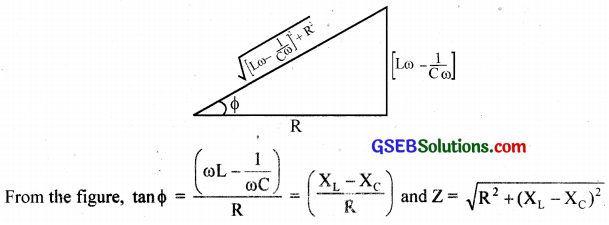
Question 7.
The impedance of a circuit may also be calculated using an impedance triangle. Explain
Answer:
Question 8.
What is the magnitude of current at that instant?
Answer:
i = im sin(ωt – F)
im = \(\frac{v_{m}}{Z}\) and \(\frac{v_{m}}{R}\) and F = 0
∴ i = im sin ωt
Question 9.
What is the instantaneous power in an ac circuit?
Answer:
Power, P = VI = vmim sinωt.sin(ωt – F) = vm im [ sin2ωt.cosF – \(\frac { 1 }{ 2 }\) sinωt sinF ]
![]()
Question 10.
In LCR series circuit, how will you calculate average power?
Answer:
Average power, Pave = \(\frac { 1 }{ 2 }\) \(\int _{ 0 }^{ T }{ P.dt }\)
= \(\frac{\mathrm{V}_{0} \mathrm{I}_{0}}{2}\)cosF
Pave = Vrms. Irms.cosF
Question 11.
What is the power in a pure resistance circuit?
Answer:
Pav = Vrms. Irms [since cosF = 1]
Question 12.
What is the power in the purely inductive circuit or capacitive circuit? Why?
Answer:
Pave = zero
Pave = Vrms. Irms cos F
Here Φ = 90° ∴ cos F = 0
Hence, Pave = 0
Question 13.
Which form of energy is stored in a charged condenser?
Answer:
Electrostatic potential energy
Question 14.
What happens when charged condenser is connected to a solenoid (inductor)?
Answer:
Electrical energy stored in the charged condenser is transferred to the inductor during the discharge of the condenser.
![]()
Question 15.
Which form of energy is stored in the inductor?
Answer:
Magnetic energy
Question 16.
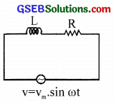
(a) Arrive at an expression for net voltage.
(b) What is the phase difference between voltage and current?
(c) What conclusion do you draw?
Answer:
(a) Voltage across the inductance = VL.
The voltage across the resistance = VR.
Since VL is out of phase by 90°, net voltage is given by V = \(\sqrt{\mathrm{V}_{\mathrm{R}}^{2}+\mathrm{V}_{\mathrm{L}}^{2}}\)
(b) The voltage across the inductance leads by a phase factor \(\frac { π }{ 2 }\) with respect to the generated e.m.f.
(c) The power consumed by the inductor is zero. Since Φ = \(\frac { π }{ 2 }\) and current in the inductor lags w.r.to voltage. Net power loss is due to resistance.
Question 17.
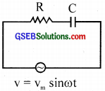
(a) Arrive at an expression for net voltage.
(b) What is the phase difference between voltage and current?
(c) What conclusion do you draw?
Answer:
(a) The net voltage, V = \(\sqrt{\mathrm{V}_{\mathrm{R}}^{2}+\mathrm{V}_{\mathrm{C}}^{2}}\)
(b) The current through capacitor leads by a phase factor = \(\frac { π }{ 2 }\).
(c) No power is consumed by capacitor. Power loss is due to resistance
Question 18.
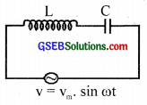
(a) With the help of the figure explains the specialty of the circuit.
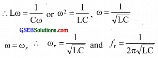
(b) Obtain an expression for resonant frequency.
Answer:
(a) The inductive voltage VL = I XL and capacitive voltage VC = l.XC is the opposite in phase. VL cancels with VC when they are equal. This state is called resonance. The amplitude of current becomes maximum. The condition is XL = XC
(b)
Question 19.
(a) What is a phasor diagram?
(b) Draw’ the phasor diagram of the series LCR series AC circuit.
(c) What is the net voltage across the inductor and capacitor at resonance?
(d) Why is a series LCR circuit called an acceptor circuit?
Answer:
(a) A diagram in which different properties of a.c circuit of current, voltage, etc. are represented by vectors with corresponding phases.
(b)
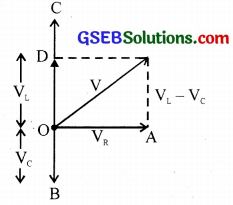
VR – Phase voltage of resistance
VL – Voltage across the inductance
VC – Voltage across capacitor
V – net voltage
(c) At resonance VL = -VC
∴ net voltage is zero.
(d) At resonance the impedance is minimum and therefore the circuit accepts maximum current through it. Hence the name acceptor circuit.
![]()
Question 20.
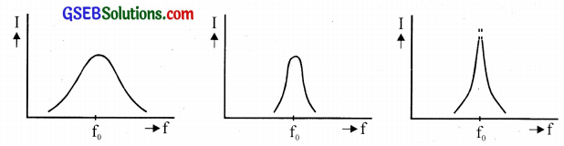
The current-frequency response curves are shown in the figures above for three LCR circuits.
(a) What is the Q-factor of the LCR circuit?
(b) Which of the curves in the above figures has highest Q value?
(c) Write an expression for the Q value.
(d) Can any of the curves shown in the figures represent the current-frequency response of a parallel LCR circuit?
Answer:
(a) The ratio of inductive reactance to resistance is called Q factor.
(b) The last one. (Figure at the right end)
(c) \(\frac { Lω }{ R }\) or \(\frac { 1 }{ CωR }\)
(d) No.
Question 21.
What is the frequency of direct current?
Answer:
Zero.
Question 22.
i = 5 sin 314t. Which is the peak value of current?
Answer:
i = im sin cot and i = 5 sin 314t
∴ Peak value of current, im = 5 A
![]()
Question 23.
Which value of current do you measure with an A.C ammeter?
Answer:
Rms value of current
Question 24.
A capacitor blocks D.C but allows A.C to pass through it. Explain why.
Answer:
Xc = \(\frac{1}{2 \pi v C}\)
For DC, υ = 0, ∴ Xc = infinite so it blocks DC
For AC, υ ≠ 0, ∴ Xc has a finite value and so it allows AC to pass through it.
Question 25.
A transformer cannot work on D.C. Why?
Answer:
If D.C voltage is applied, then magnetic flux linked with the coil will not vary with time and hence there is no induced emf. Hence the reason.
Question 26.
What is the function of a choke coil in a fluorescent tube?
Answer:
It decreases current in the circuit without wastage of electrical energy in the form of heat.
![]()
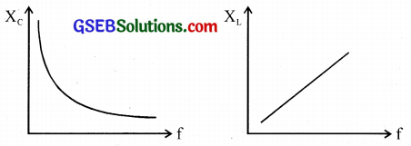
Question 27.
Draw the graph showing the variation of the reactance of (a) C and (b) L with frequency υ of an A.C circuit.
Answer:
(a) Xc = \(\frac{1}{2 \pi v C}\)
∴ Xc ∝ \(\frac { 1 }{ υ }\)
(b) XL= 2πυL
Xc ∝ υ
Question 28.
Which is more dangerous, A.C or D.C? Why?
Answer:
AC is more dangerous than D.C of the same voltage. Because the peak value of A.C is more than the indicated value,
Example: Peak value of D.C = 220 V
Then value of A.C = 220\(\sqrt{2}\) = 311V